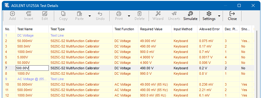
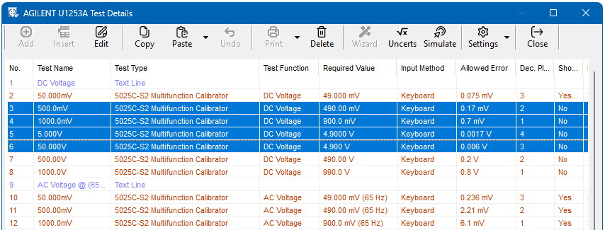
Once the Procedure Details have been set, the Tests can be entered using the screen shown below. This is called from the Procedure Selection screen by clicking on the ‘Tests’ button. It is used to Add, Edit and Delete tests. The tests are listed in numeric order and the main parameters for each test are given to help identification and checking.
To Add a new test at the end of the list click the ‘Add’ button.
To Insert a test, you must first highlight a test by clicking on it, then click on the ’Insert’ button.
After you have entered and approved the test details the test will be placed in front of
(i.e. above) the highlighted test.
To Delete a test you must first highlight it, then click on the ‘Delete’ button – a final warning is given before the test is actually deleted.
A Copy and Paste option is also provided to speed up the data entry for tests with similar content. Highlight the test(s) that you want to copy and click on the ‘Copy’ button (this copies all the data for that test into a memory buffer). Highlight another test and then click on the ’Paste’ button, this will bring up a menu which allows either :
- Inserting the pasted test before the highlighted one.
- Overwriting the highlighted one.
- Placing it at the end of the list. Once pasted, this test can itself be selected and edited in the normal way.
Note: If more than 1 tests has been selected the only option available is Add to end of Test list.
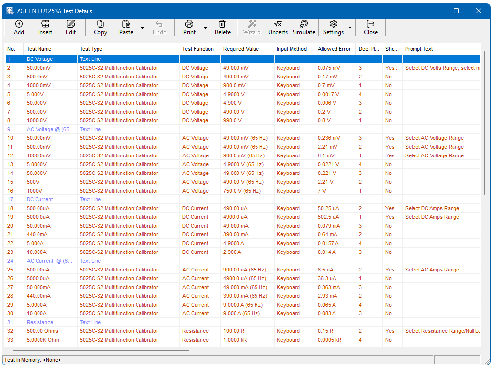
All tests are identified numerically and the first test is always No. 1. The sequence of testing in CalRun is always strictly in test number order. When tests are inserted and/or deleted, the numbering is automatically adjusted to ensure that the list is always complete and in numerical order.
The ‘Add’ and ‘Insert’ buttons will bring up the Test Type entry screen before the Test Details screen. The ‘Edit’ button will go directly to the Test Details screen.
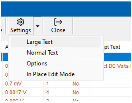
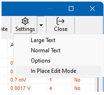
Large / Normal Text: The test list view can be altered to show a large or standard font size. This can help with reading or allow more test rows on the screen.
In Place Edit Mode is only available when the language setting is English and the Advanced Procedure Editing option is enabled in System Setup > Options.
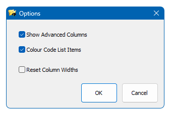
Options
Show advanced Columns: If required extra columns in the list can be shown. These are ‘Auto Proceed’, ‘Recalc From Test’, ‘DMM Range’, ‘RS232 Command’ and ‘Modified Date’.
Colour Code List Items: This is used to help identify different test types.
Reset Column Widths: Column widths are saved each time they are adjusted. If required these can be set to back to the default widths.
In Place Edit Mode
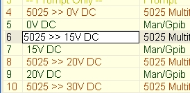
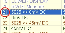
To aid the procedure editing process certain data can be edited ‘In Place’ directly from the test list.
Once in ‘In Place Edit Mode’ click on the data you wish to edit. (Note: not all data can be edited)
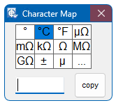
Character Map and Extended Symbols
Throughout various sections in EasyCal Symbol feature is available. Click on this and a character map of useful symbols which are not commonly available on a standard keyboard to be entered, such as the ohms symbol, will appear. Use the copy button and then paste where required.
Click on the 3 dots to start Windows in-built character map program.

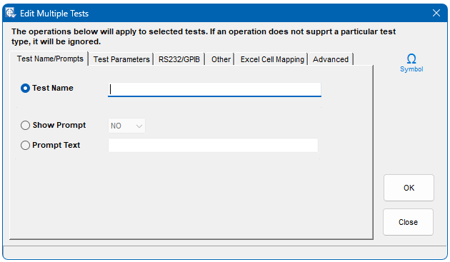
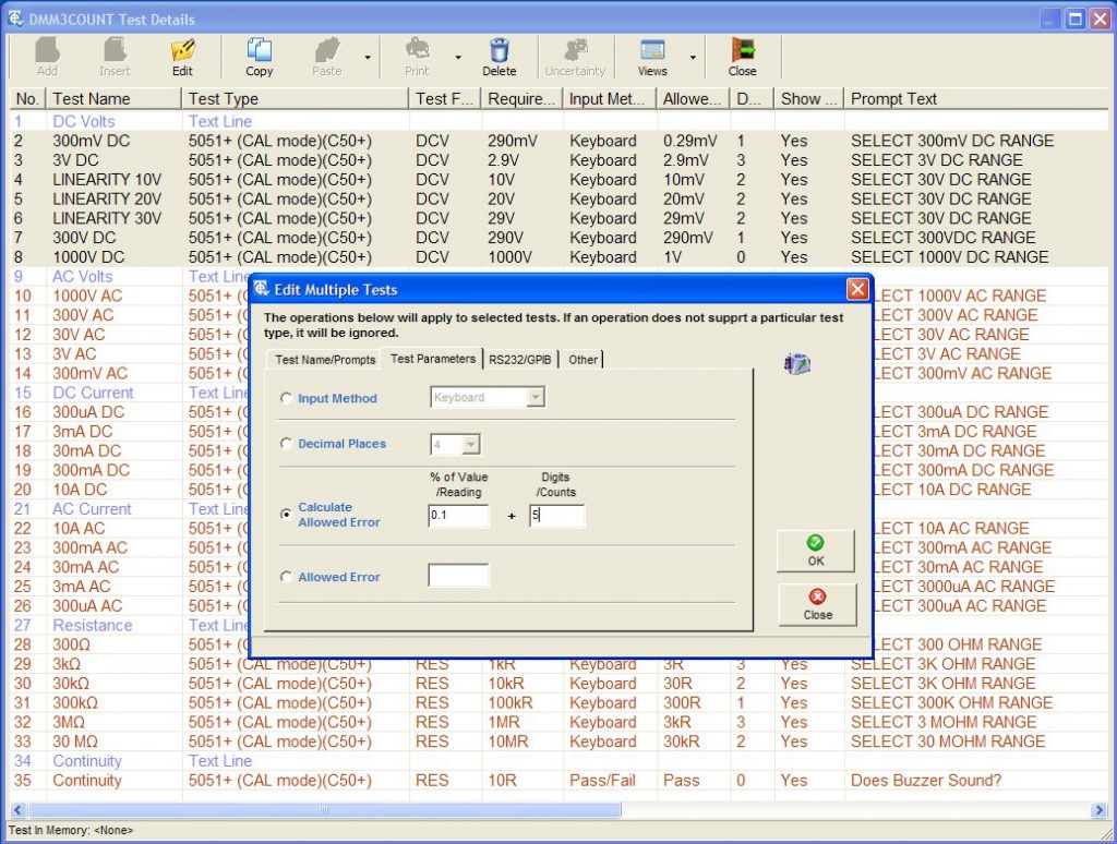
Multiple Test Edit
If required any number of tests can be globally edited. For example, if the ‘Input Method’ for a number of tests needs to be changed, highlight the tests and click edit. The ‘Edit Multiple Test’ window will appear. Select the type of ‘Input Method’ required and click OK. It is recommended that a copy of the procedure is taken before attempting multiple edit as there is no ‘undo’ feature. (Note the option for Advanced Procedure Edit must be enabled in System Setup > Options)
Paste Special
To quickly and easily create procedures a special pasting function is available. This feature is accessed from the paste button drop-down menu. The selected test(s) can be repeated and added to the end of the test procedure.
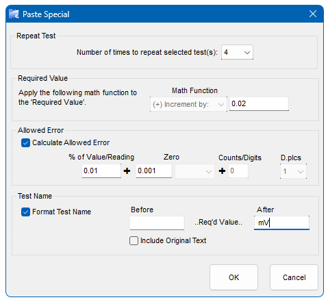
The selected test’s required (setup) value can be incremented or multiplied by the value entered. A calculated allowed error can be applied to each test repeated, which is based on the incremented or multiplied required value. The test name can also be formatted using the required value. Text can be entered before and after the required value which will be repeated for each test.
Note: The maximum number of characters in the test name is 20. If longer EasyCal will automatically shorten the test name.
Note: Advanced Procedure Editing Must be enabled in System Setup > Options
Details
A report of the basic procedure information
is produced.
Full Details
A report of all the procedure details is produced.
Specifications
A report showing the specification and calculation data is produced.
Example Certificate
A preview of the certificate is produced. This is useful when using the certificate formatting features.
If column 7 in the procedure details is selected as ‘Uncertainty’ the Uncertainties button in the toolbar will become active.
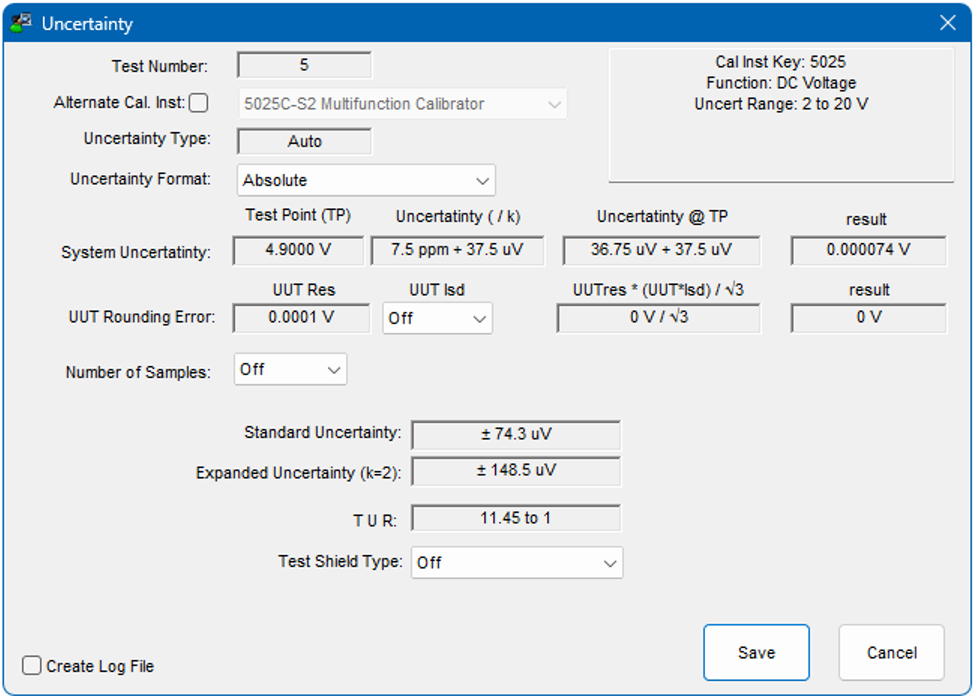
If the required value falls into the uncertainty range for the function then the uncertainty will be automatically applied. This will occur to all tests in the procedure where a valid uncertainty for the required value and function is found.
It is also possible to automatically apply uncertainties to a certificate using PrintCert.
Note: The uncertainty range applied to the required value is greater than the lower value (specified in the uncertainty for the calibrating instrument) and less than or equal to the upper value.
The uncertainty for each test can be reviewed by viewing the test data. The value can be manually edited if required.
Simulate
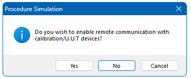
This performs a simulated calibration run, without the need to save results. The option to disable communication (RS232 or GPIB) to a calibrator or device under test is available. These means a procedure can be tested easily. To edit test parameters while running the procedure, switch between the 2 programs using the task bar.
NOTE: Is it not possible Add or delete tests whilst running in simulation mode.
Add
This screen enables additional test and control functions to be included in the sequence of tests and also provides a facility for the inclusion of explanatory text in the Certificate Report when printed. The type of input is determined by selection of one of the three buttons on the left side of the screen. Further input screens are then displayed depending on the selection as described in the following paragraphs.
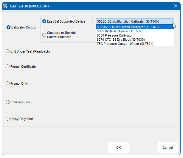
Calibrator Control
Provides the facility to define tests to be performed using calibration equipment either from Time Electronics or Other Equipment. The required option is selected using the appropriate button to the right of the Full Test button.
- Time Electronics’ Device option – EasyCal has internal drivers written to automatically control instruments manufactured by Time Electronics Ltd. The drop down list shows which instruments are available as defined in EasyEdit > System Setup > Calibration Instruments.
- Standard or GPIB/RS232 Device – These tests are specified for test/control where EasyCal’s internal drivers are not used.
Again, this drop down list displays calibration instruments/standards that have been specified in EasyEdit > System Setup > Calibration Instruments.
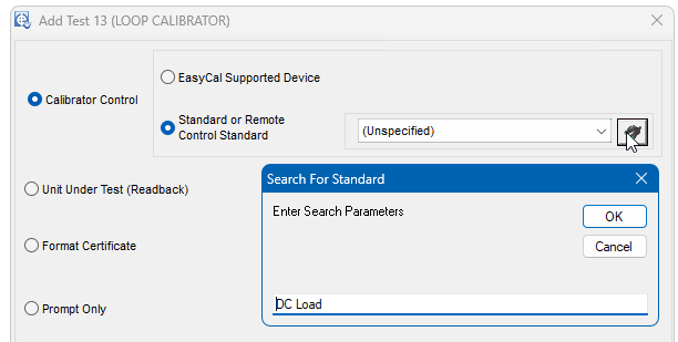
Search for Standards
When selecting a Standard or Remote Control Standard a search feature is available. Enter any part of the description or ID in the search box to find an instrument in the drop down list.
Additional information about the Standard is also shown by holding the mouse pointer over the drop down list.
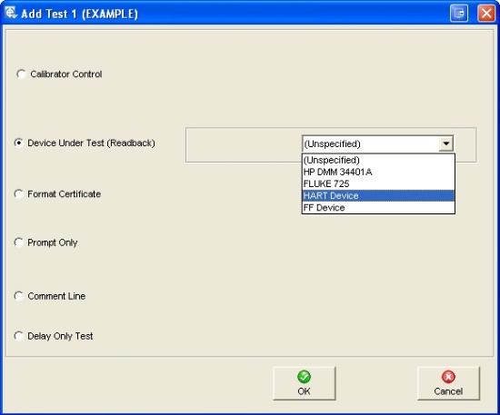
Device Under Test (Readback)
If required, a separate D.U.T test can be performed. This is normally the case when a communication protocol is used, for example HART or a Readback Driver has been specified (see chapter 8 – Readback drivers). Usually the test prior to the DUT test is a calibrator ‘setup only’ test.
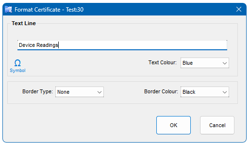
Format Certificate
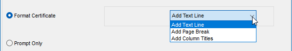
Text Line
When a text line is entered, the option to add boarders and colours is available.
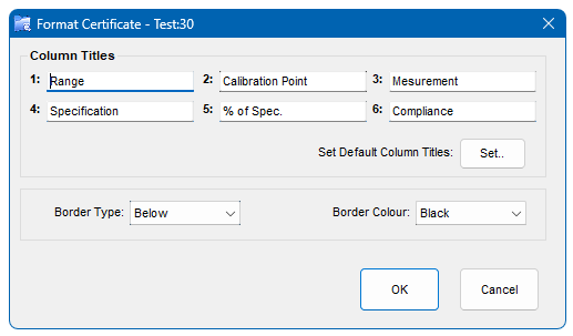
Column Titles
Column titles can be entered on a test by test basis. This allows a certificate which contains different test types to be formatted effectively. If this option is used the main column titles set in the procedure details can be left blank.
This type does not affect the calibration run and no commands are sent. It simply inserts a line of text in the Calibration Certificate at the place it occurs in the list of tests – maximum length is 50 characters.
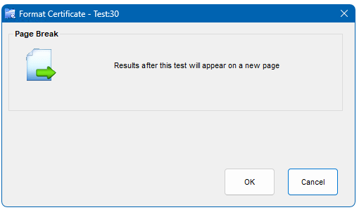
Page Break
This is very useful in producing tidy certificates and allows a group of results to be printed together on one page instead of being split over two
Prompt Only
The prompt text appears on the screen before the test is performed. It is also possible to set a prompt from each individual test window.
Image Prompts
Used to display an image (.bmp & .jpg) before the test is performed. These pictures can indicate lead connections and switch positions for the instrument being calibrated. Image prompts can be any aspect ratio. The window is sizable and the image scales to the size of the window. The picture prompt is also shown in this format during a Calibration Run (CalRun).
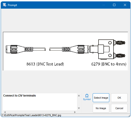
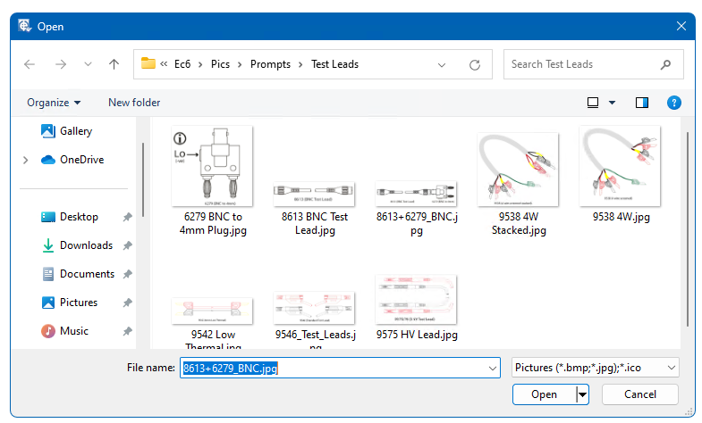
A set of Time Electronics test lead images is provided to assist with procedure development. These are located in the Pics\Prompts\Test leads directory.
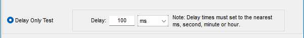
Delay Only Test
Allows a user defined delay to occur during the calibration run. No control commands are sent by EasyCal (CalRun). The delay can be set in milliseconds, seconds, minutes and hours. Decimal values are not allowed. For example to set 1.5 hours, 90 minutes must be entered. In semi-automatic testing/calibration systems delays are sometimes required to allow time for measuring equipment, such as temperature baths, to stabilise.

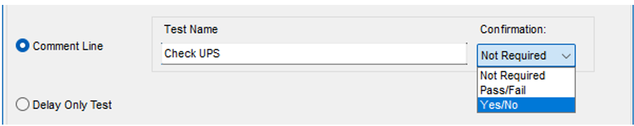
Comment Line
A simple comment test can be performed. The user is prompted to enter a comment during the test run. The type of confirmation, if required, is selected from the drop down menu.
Create/Edit Test Information
Depending on the test type selected, different information (fields) will need to be completed.
However, apart from the ‘Delay Only’ and ‘Line of text..’ tests described earlier, there are several data fields which are common to all tests.
These are as follows:
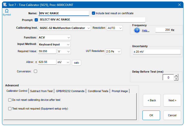
Name
The name (mandatory) of the test as it appears on the screen during the Calibration Run and on the Calibration Certificate. It is a free form entry field with a 20 character maximum length – spaces and dashes are allowed.
Prompt
This text appears on the screen before the test is performed. It can be disabled by un-ticking the box next to Prompt, in which case the text box is not displayed.
Function
This sets the function that is available for the calibrating equipment being used.
The functions for TE equipment are predefined.
If 5051 Source Mode is being used EasyCal detects which options/functions are installed.
If a 5025 is being used it is possible to have a function in the list which your 5025 will not support.
If a Standard or GPIB/RS232 calibrating instrument is being used (as specified in System Setup > Calibration Instruments) a list of generic functions will appear. This allows easy selection of units and their symbols.
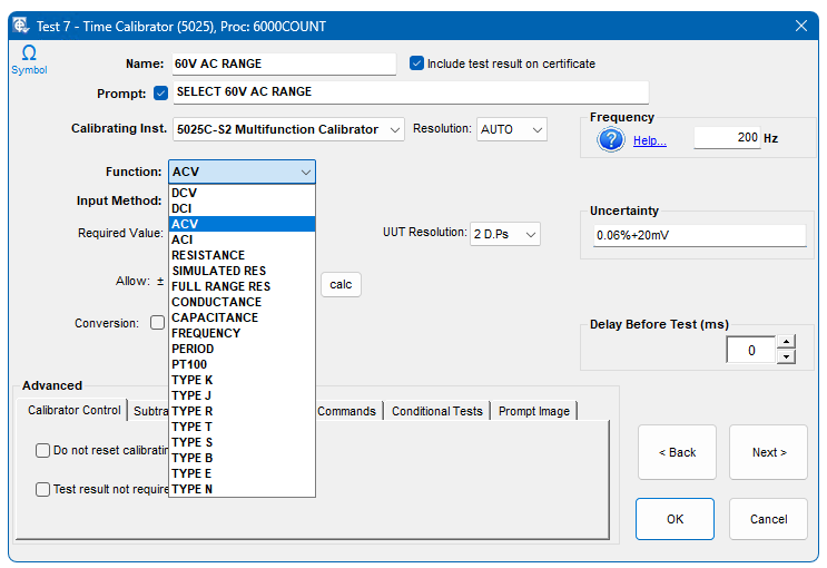
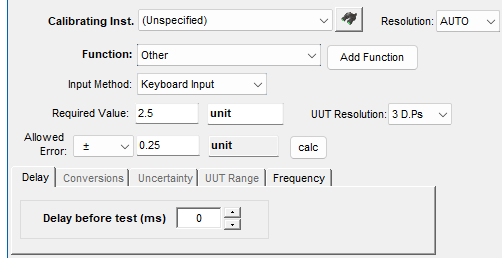
Additional functions and units can be created by clicking on the Add Function button. ‘Scalar Tables’ can be created and modified from this section. For further information see chapter 8.4 Scalar Tables.
To simply enter a unit of measure which is not list select ‘other’ from the ‘drop down’ menu. Units can then be entered manually.
Required Value
This is the value the test is to output or measure.
!!! Allowed Error TOLERANCE TYPES
Here the Allowed Error or ‘Tolerance’ is entered for the test. The calculator can be used to obtain this value.
Decimal Places
Thisfield controls the number of decimal places shown during a Calibration Run and on the Certificate. You should therefore use Decimal Places entry to match the number of decimal places displayed on the screen of the DMM/instruments under test.
Delay before test
Specifies the delay value in milli-seconds.
Frequency
If using a Time Electronics 5025 or 5051/7051 Cal Mode the output frequency is set. On the certificate the frequency will be shown in brackets after the required value.
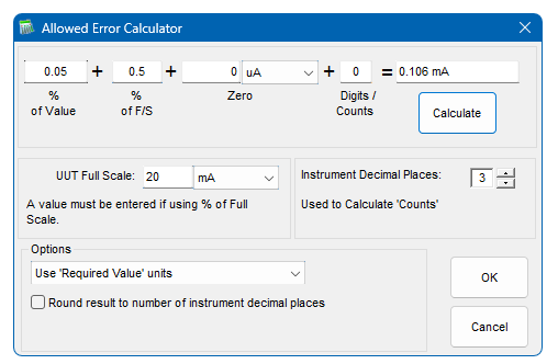
Results Calculator
Can be used to calculate the deviation allowed from zero of an instrument based on the nominal (required) value and the instrument’s range (Tolerance).
Please note that if % of Range/Full Scale is used, it is necessary to complete the ‘Instrument Range’ field on the results calculator.
Digits/Counts’ are as used by most multimeter manufacturers to specify accuracy along with a % of Reading figure. The number of decimal places, by default, is set by the value entered in the main edit window.
The option to use the same units as the set up value can be chosen. Also the option to round the calculated error to the number of decimal places is available. This is useful when writing a procedure for a digital device. This can be set as default in EasyEdit>System Setup>Option>Advanced Program Options.
Conversions
Sometimes a test is required that outputs/reads a value that represents another parameter, e.g. a test that reads a resistance which represents a temperature from a PT-100 sensor element. The Conversion Value option is available for all TE 502x/5018/5051 Cal Mode (source) tests and TE 5075/5051 DMM Mode (measure) tests. For these types of test, the Conversions box is ticked, and a further line of entry boxes is displayed
Conversion Tables
EasyCal contains a set of standard conversion tables.
Thermocouple (DC Volts) Types J, K, B, E, N, R, S, and T. (°C, °F or Kelvin)
PRT (Resistance)- PT100, PT1000 and PT200 Devices. (°C, °F or Kelvin.)
50 Turn Clamp Adaptor (DC/AC Amps) 50X Multiplier Clamp, A
AC Current Transformer 100A (AC Amps) 5X Multiplier C.T, A
5025 and 5051 Calibrators must be fitted with simulated resistance or advanced resistance options to source PRT values.
Pt100 Measurement Example
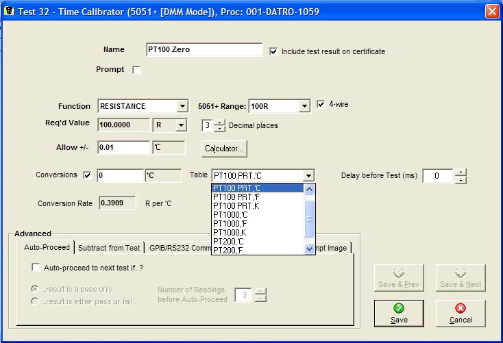
The example above shows a 5051 DMM Mode (measure) test, using the ‘PT100 °C’ Conversion Table, to read the output of a PT-100 simulator at 0°C
The selected Conversion Table sets the required value (Required Value) in relation to the Conversion value entered. In the example above a conversion rate of 0.390Ω per °C is applied.
Thermocouple Conversion Example
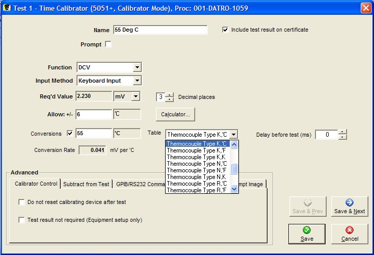
This example shows a 5051 Cal Mode (source) test, using the ‘Thermocouple Type K °C’ Conversion Table to set -55°C. (Also note that a ‘Subtract result of test’ is used for Cold Junction Compensation-see Subtract from test of test section below).
Clamp Meter Adaptor 50 Turns
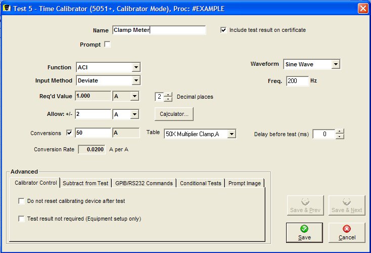
The 50 Turn clamp meter conversion table applies a linear factor of 0.02 Amps per Amp.
Conversions can also be used without a Conversion Table.
If ‘Conversion Table’ is set to (None) the Required Value, Conversion Rate, Represents Value and units are entered.
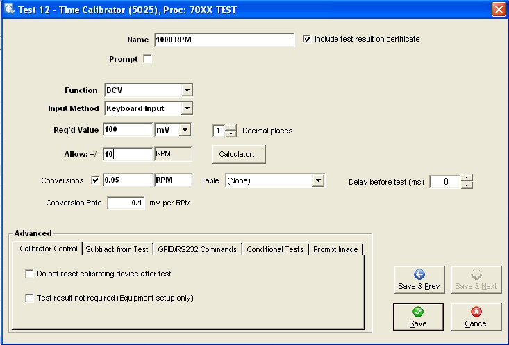
This example shows a simple conversion from mV to RPM.
For more complex and non linear Conversion Rates a ‘User Conversion Table’ can be created – See Error! Reference source not found. Section Error! Reference source not found. for details.
Note: When using the ‘Conversion’ option, the Allowed Error and Calculator use the Converted Value Units. Converted Value and Units will appear on the Calibration Certificate, and the Calibration Run screens will display using the Converted Value and Units.
Advanced
Calibrator Control
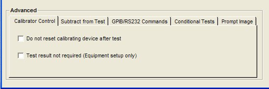
Test result not required
The appearance of the centre section of the screen depends on whether or not this box is ticked,
- Not Required (i.e. box ticked) – the test is only setting up the instruments/equipment either directly or via the GPIB/RS232. No measurement will be made and therefore no result is required. When this is selected, the specification entry/result details boxes disappear leaving only the GPIB/Serial Command area within the ‘Advance Options’ section at the bottom requiring data entry. Details of the command formats and protocol for this are described later.
- Required (i.e. box un-ticked) – the measured or actual value is obtained by the specified Input Methodand it is compared with the specified Required Value to determine whether it is within specification. The result is calculated and is initially stored in a temporary test results database. After all the tests have been completed the user has the option to transfer the results to the permanent results database
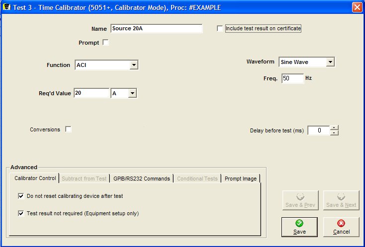
Do not reset calibrating device after test
Ticking this box prevents the calibrating device from being reset to zero at the completion of the test.
This is useful when producing ‘Source & Measure’ tests. For example when testing a clamp meters analogue output with a 5051.
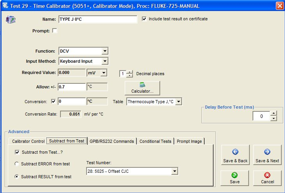
Subtract from test of test
Re-calculate the current test by subtracting the error or result of a previous specified test. This is often used to adjust resistance readings by subtracting the end and lead resistance (null) if calibrating a decade box from example, or for Thermocouple Cold Junction Compensation. Normally this is N/A, which means, don’t recalculate.
Subtracting the Cold Junction Value on a Thermocouple Meter
The images below show the settings for subtracting the ambient temperature (cold junction) from a thermocouple meter.
The first test requires the ambient temperature (cold junction) to be entered. This test will not be shown on the Certificate, note ‘Include test results on certificate’ is not ticked.
The output from the calibrator must be set to 0ºC (or 0mV). A wide allowed error is set to +/- 30 ºC. This allows for ambient temperature to be entered.
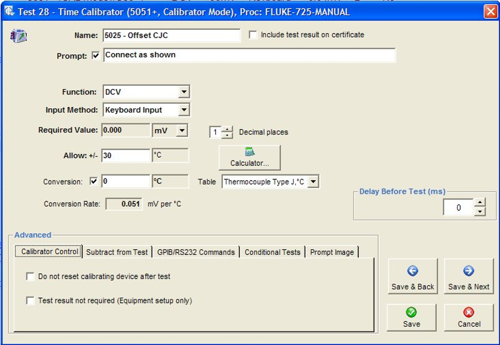
Subsequent tests have the ‘result’ from test 28 subtracted.
GPIB/RS-232 Commands
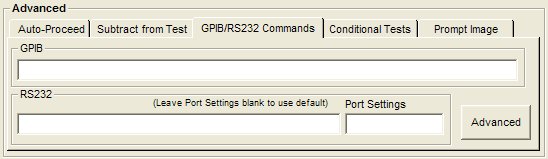
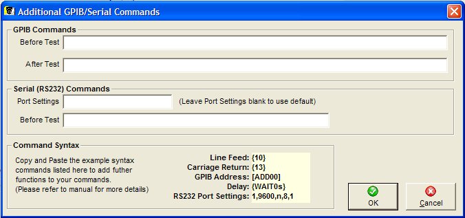
GPIB Commands
GPIB Commands can be executed before and after a test. If editing the command from the main test window, the command before test can be entered directly.
The GPIB Commands line can contain one or more commands to send to one or more GPIB devices. Each individual command has the following syntax:
[ADD<addr>] <Command> where <addr> is the GPIB address of the device and <Command> is the string containing the command to be sent, eg ADD7R5 will send the command R5 to the GPIB device with address 7.
If the ‘ADD<addr>‘ is not specified in the command line and a ‘<Command>‘ only specified, EasyCal will send the command to default address which is the system instrument/GPIB device specified in the test header.
Each <Command> should contain the string of characters to be sent to the GPIB device. Non printing characters, e.g. CR or LF, can also be sent but their ascii numerical value must be specified and enclosed in { } brackets e.g. W7{13}R5 sends W7(carriage return)R5.
GPIB Command termination
In general GPIB devices will expect to see a character at the end of the command string which indicates the end of the command. Since the GPIB bus is asynchronous, devices on it have no way of determining the end of commands they are receiving other than by looking for the terminating character (terminator) or, by interrogating the hardware GPIB line called ’EOI’. If the GPIB device does not use either of these methods to sense the end of command, it will often have what is known as a ’time out’ function. This means that if, after a fixed period of time (e.g. 1/2 sec), it sees no more command characters it will assume that the command is complete. This is considered a very unsafe way to communicate over the GPIB particularly when there is more than one GPIB device on the bus. It also makes it much more difficult for the GPIB controller (in the PC running EasyCal) to keep control of the bus.
It is important to identify which terminator to use. EasyCal allows any ASCII character (printing or non-printing) to be used. If it is a non-printing character it must be specified as its ASCII number and enclosed in { } brackets. e.g. R5{10} adds line feed as a terminator. Note that the { } method can also be used to send any non-printing character, not just the terminator. By default EasyCal automatically enables the hardware terminator GPIB ‘EOI’. This is one of the GPIB lines and is used to determine ’End Of Information’. Some GPIB devices will use this as their indication of end of command and will not require a terminating character to be appended to the command string. However, in some cases, older GPIB instruments can get confused if the ’EOI’ line is used and therefore EasyCal allows its use to be disabled. This is done by specifying {NOEOI} at the end of the command string. eg W5{NOEOI} {10} will send the command W5 followed by (line feed) but will not operate the ’EOI’ line on the GPIB bus.
Serial (RS-232) Commands
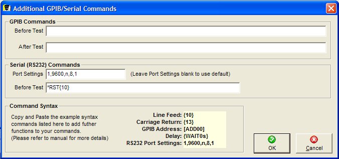
Port settings format: <com>, <baud>, <parity>, <databits>, <stopbits>. If only <com> is specified the other parameters default to 9600,N,8,1. As with GPIB, non-printing characters must be enclosed in { }. It should be noted that only one RS-232 instrument can be driven with the command string and it is sent before the test. In the example above “*RST” followed by non-printing character ASCII10 has been sent to COM1 at 9600 baud with NO parity, 8 data bits and 1 stop bit.
Note: Both GPIB and RS-232 instruments can be driven in the same test.
Example of multiple GPIB and an RS232 command
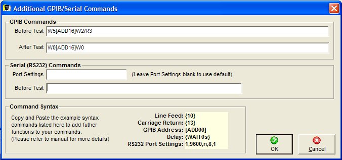
In the example above, the command “W5” is sent to the instrument with GPIB the default address (as set in the Calibration Instruments section of EasyEdit Set Up. This is followed “W2/R3” sent to the instrument with GPIB address 16. After the test has been completed, “W0” is sent to the default address followed by W0 to address 16.
Scripts
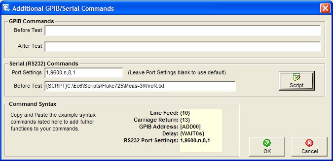
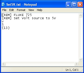
For more complex RS232 commands a script can be written. The file format is a simple text document (Scipt.txt for example).
In this example a Fluke 725 is set to source 5V
The [REM] statement is used to add remarks to the scripts,
First the character ‘v’ is sent, then ‘5’ then the line feed character {13}.
Conditional Test Control
To activate conditional test control, tick the box labelled “Conditional Test Control” in the bottom-right corner of the test details entry screen and click the “Details” button. A setup screen is displayed as shown below:
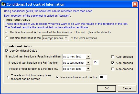
Repeated Test Statistics
EasyCal can repeat the same test or group of tests using Conditional Gotos option
You can choose to store the result of repeated tests as one of the following statistical calculations:
- Average (mean) of test results
- RMS (Root Mean Square) of test results
- Minimum test result
- Maximum test result
In addition, there is an option to set an upper limit on the number of iterations of the test.
Prompt Image
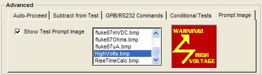
Used to request the display of a bitmap image (.bmp & .jpg) before the test is performed. A digital camera can provide these pictures to indicate lead connections and switch positions for the instrument being calibrated.
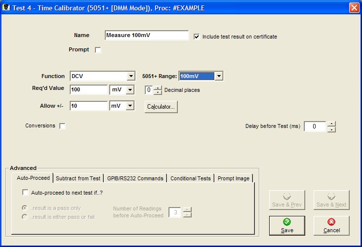
Auto Proceed
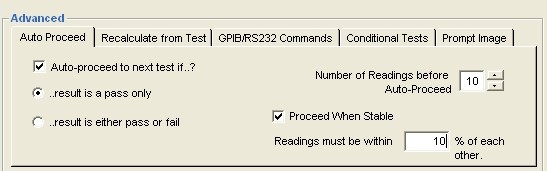
For 5051 DMM Mode, 5075 and Readback tests the option to ‘Auto-Proceed’ is available.
This means that the procedure will automatically step to the next test depending on the conditions set in this window.
Proceed When Stable
Normally EasyCal will only allow auto-proceed if the last 2 reading are within 25% of each other. Using the ‘Proceed When Stable’ feature it is now possible to set the value where up to 50 readings must be within a percentage of each other. During a calibration run EasyCal records these readings and will only proceed to the next test if each of these readings (‘Number of Reading Before Auto-Proceed) are within the specified percentage of each other
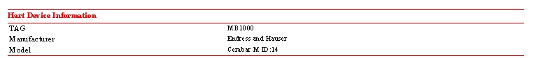
Hart and FF Devices
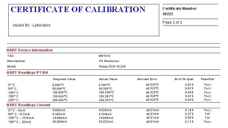
When testing a HART or Fieldbus device a collection of commands are available. To setup connection to HART and Fieldbus devices separate applications are used; EasyHART and EasyFF. Please see the separate application note for more information.
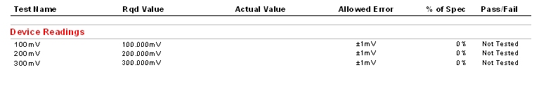
Some commands such as ‘Read Tag’ simply return a text based result and is shown on the certificate as below.
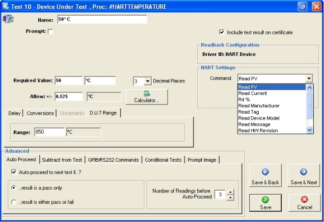
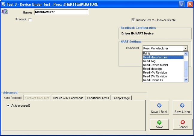
The commands ‘Read PV’, ‘Read Current’ and ‘Read %’ (if available from the sensor) return a numeric value and is shown on the certificate as standard test result.
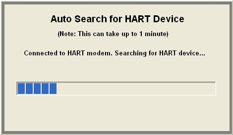
For Hart settings the com. port used is set in EasyHart. The device poll address is also set in EasyHart. This can be set to AUTO if required. In this mode EasyCal will attempt to locate the sensors poll address automatically.
Search
When there are a large number of procedures in the database, the search facility may be used to aid selection. Selection by Procedure Name, Instrument Type, Manufacturer and Model is supported. Drop-Down lists for each give the user a choice from alphabetic listings compiled from the information already in the database.
Print List
This prints a detailed list of the procedures shown in the window. (An example is shown in Error! Reference source not found.).
Copy
Here you are presented with a list of current procedures. Select the procedure you wish to duplicate and press OK. You will then be asked to give the new procedure a name. Once the duplication is complete the procedure can be edited in the normal manor.
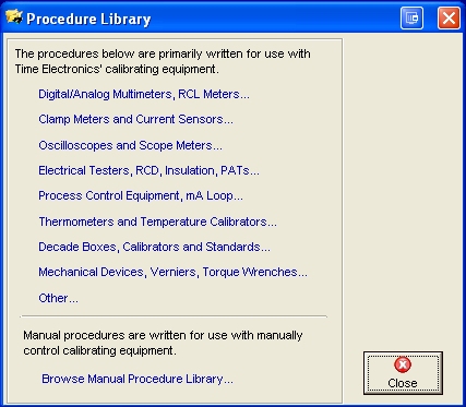
Library
Included in EasyCal are a number of procedure libraries containing pre-written procedures.
These can be imported and modified as required. Select the procedure required from the listing window, or alternatively search for the procedure in the normal manor. The original will remain unchanged. For a full listing see Error! Reference source not found.
Import
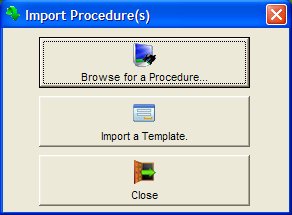
Browse for a Procedure
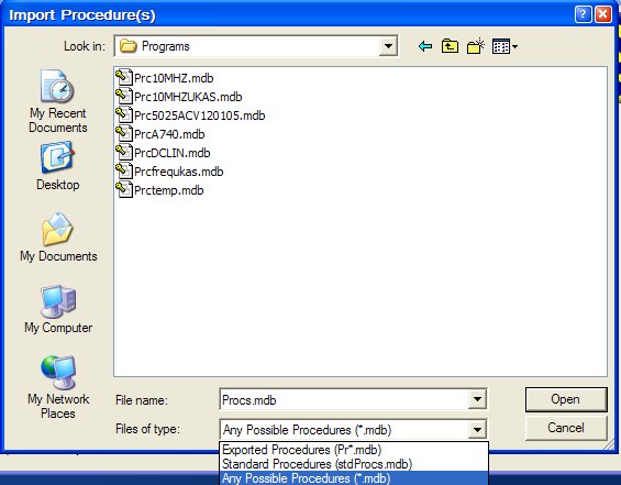
Use this to import data from any EasyCal procedure database. Exported procedure databases are usually prefixed with the letters ‘prc’. Using the ‘Files of type’ drop down menu any possible EasyCal procedure database can be imported, even if it is not prefixed with the letters ‘prc’
After selecting a database file a confirmation window will appear, click OK to continue.
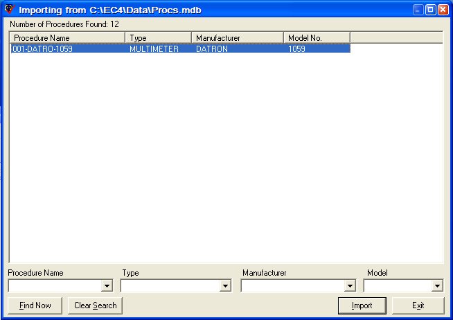
A window will then appear listing the procedures available for import – you may use the search facilities in the same way as they are used elsewhere in EasyCal.
Highlight the procedures that you want to import (the ctrl & shift buttons can used to select multiple items). Then click Import to continue. The import will begin.
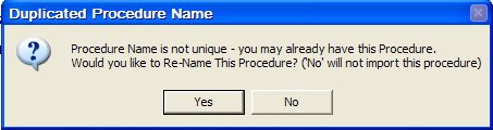
Duplicate Procedure Names are not allowed – if EasyCal tries to import a record which already has the same ID it will ask you if you want to import it:
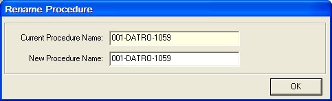
If you click Yes, it will then prompt you for a new ID or Procedure Name. You must change the Procedure Name to a name that is not already in use. At the end of the import, the number of records imported will be displayed.
Import a Template
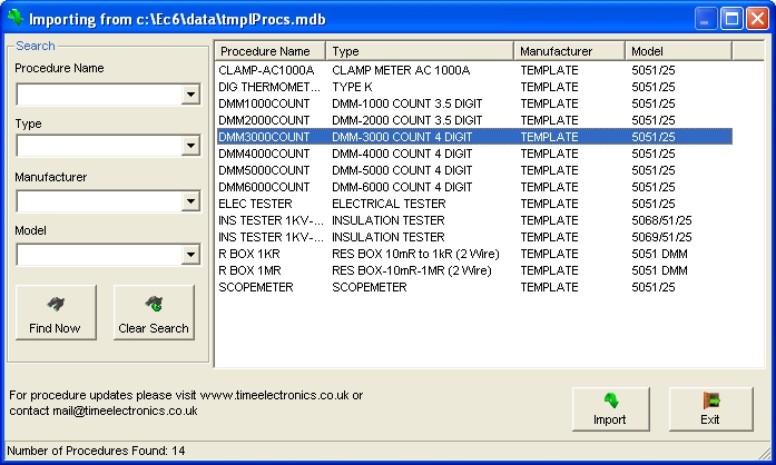
Procedure templates can be used a basis to quickly create a new procedure. Using the advanced procedure editing features parameters for a number of tests can be altered in one process. The model number indicates the type of Calibrator the template is designed for.
For example a 3000 Count, 4 Digit DMM.
Note: Advanced Procedure editing must be enabled in EasyEdit>System Setup>Options
To modify the ‘Allowed Error’ for all DC Voltage tests, highlight the required tests. Click Edit, the Edit Multiple Tests window will appear. Enter the specification details. In the example above the specification is 0.1% of reading + 5 counts. The allowed error for all highlighted tests will now be set as required.
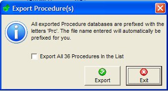
Export
Either the selected procedure or entire list can be exported to a database file. This file can then be used by other EasyCal users to import procedures. Note all exported procedures will be prefixed with Prc