First of all install EasyCal and the Agilent GPIB Card. To control the fluke 725 over RS232 a special Fluke cable is required. We have supplied this. We can also produce more cables if required. The installation of EasyCal is preconfigured for use with your 5025, 5075 & Fluke 725 and the procedure for the Fluke 725 has been pre-written. There are some parameters which are detailed to your PC, such as communication ports. The procedures have been written assuming the 725 is on comm. 1. If possible please connect the fluke 725 to comm. 1. This means that very little procedure editing will be required. To set the correct comm. port for the 5025 please follow these instructions:
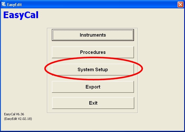
Start EasyEdit, and select System Setup
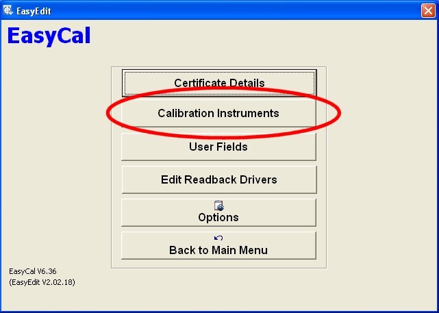
Select Calibration Instruments
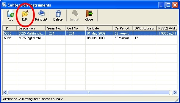
Select the 5025 from the list.
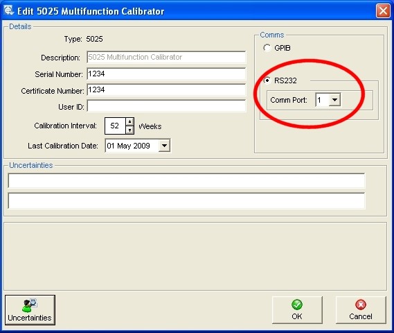
Select the correct comm. port and click OK.
The 5075 has been preconfigured to GPIB address 17. The Agilent software will not automatically detect the 5075. This is not a problem, and is quite common. (An Agilent 3458A DMM does not auto detect.)
Changing the Fluke 725 Comm Port Setting
If this is required, then please inform Time Electronics, we can then quickly edit the tests and produce a new procedure. Alternatively instructions are detailed further on in this document.
The Tests
The series of tests performed are taken from the Fluke 725 calibration manual – verification section. The following instructions show how the procedure is created.
Measure Tests
Enter EasyEdit > Procedures > Select the Fluke 725-Auto Procedure and click Tests
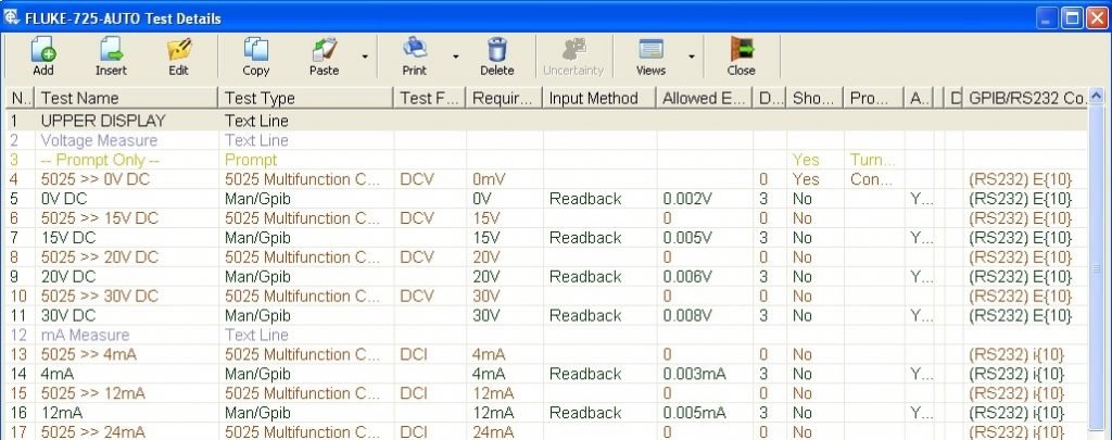
The first sets of tests are for the ‘Upper Display’ Measure Mode. The method used is to output a value from the 5025 (e.g test 6 ‘5025>>15V DC’), then record the value on the Fluke 725 using RS232 and Readback as shown in test 7.
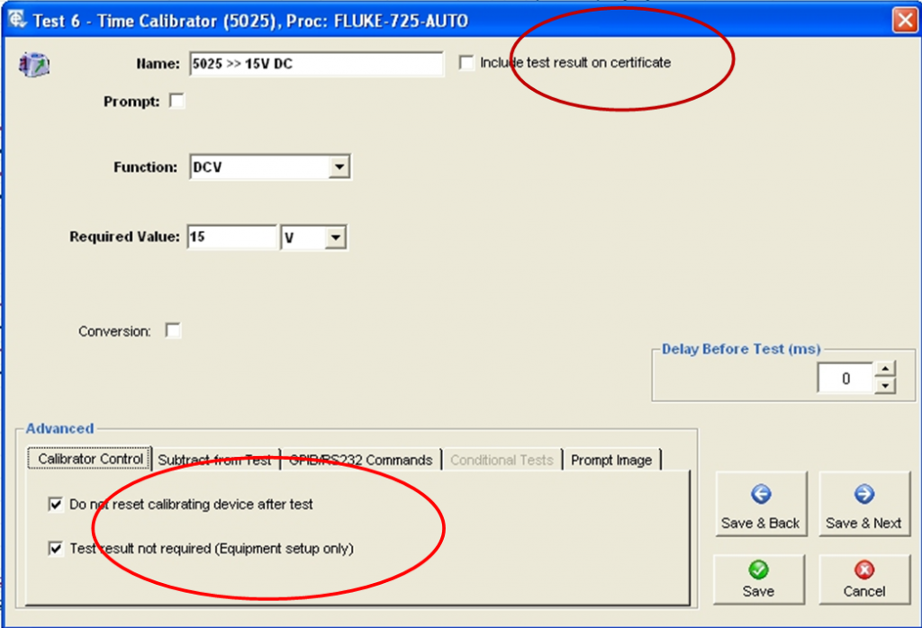
Above is the test window for the 5025 source 15V. The options are set for the 5025 (calibrator) to ‘Output Only’. Also the 5025 output must remain on for the next test. As this is a ‘Setup Only Test’ it is not required to be shown on the Certificate.
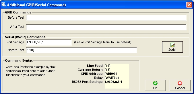
Under the GPIB/RS232 Command section the command ‘E’ (followed by the ‘line feed’ terminating character {10}) is also sent to the Fluke 725 during this test. This sets the 725 to Upper Display Measure Volts Mode. Although this command is repeated in the next test, it is wise to set the Fluke to the correct measurement mode before the 5025 outputs it’s signal.
The comm port for the 725 is defined as 1 in the settings 1,9600,n,8,1. If the comm port is different this setting must be changed. (See How To Change Comm Port for RS232 Command).
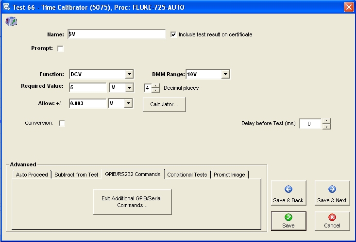
The next test sets the Fluke 725 to the required range and reads back the data shown on the display.
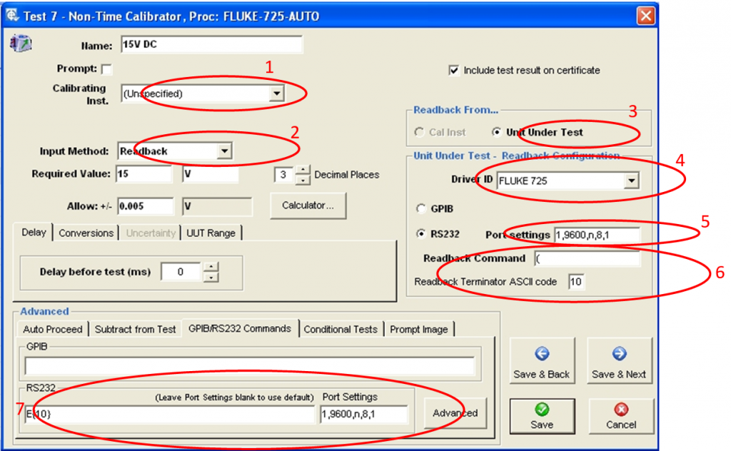
- Calibrating Instrument is set to Unspecified. This is done because a calibrating instrument is not actually used for this test.
- Input Method is set to Readback. This enables the Readback function options (3,4,5, & 6) in the right hand side of the window.
- Readback From. This specifies that Readback will be from the Unit Under Test
- Driver ID This is pre-set in EasyEdit>System Setup>Readback Instruments. The driver converts data from the UUT into readable and scalable values.
- Port Settings and Readback Command. The port is set to the comm. port for the Fluke 725. If the comm. port for the Fluke 725 is not comm. 1, this must be changed for every test than requires Readback from the Fluke 725. NOTE: This is not the same as the RS232 Port Setting for GPIB/RS232 commands (as shown in 7).
- Readback Command. This is the command sent to the Fluke 725. As stated in the Fluke 725 calibration manual, to request the 725 to ‘Broadcast’ the most recent upper display value without units, send the character “(“. If the lower display value is required the character “)” is sent.
- GPIB/RS232 Commands. Here the command to set the measurement function to Volts on the Fluke 725 is sent. This is already done in the previous 5025 Setup Only Test, but to make sure the range has been set, it is sent again. To change the comm. port setting for this section please see ‘How To Change Comm Port for RS232 Command’.
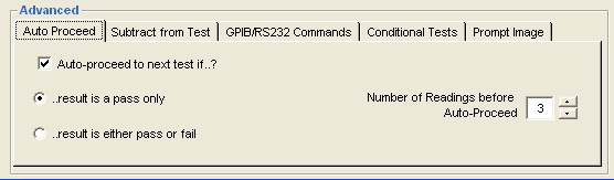
Auto Proceed.
The test is set to automatically continue to the next test after 3 ‘in specification’ readings are made. It is possible to change the number of readings before Auto-Proceed. Also the function can be set to auto proceed whatever the reading (either pass or fail).
Source Tests
A 5075 DMM is used to verify the Fluke 725 source functions.
The test window for the 5075 is shown above. Reading back from the 5075 over GPIB is automated. Standard test parameters are entered here. Also Auto – Proceed is used to automatically step to the next test.
Scripts
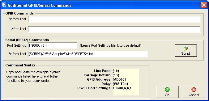
To control the 725’s source functions scripts are used. This allows multiple commands to be sent from one test. These scripts are located in c:\ec6\scripts\fluke725. The file format of the script is a simple text document. Each function has a separate script.
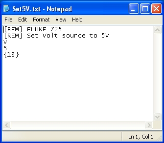
In this example the Fluke 725 is set to source 5V.
The [REM] statement is used to add remarks to the script. The character ‘v’ is sent to set the function to Volts. The character ‘5’ is sent to set the source value to 5. Finally the Carriage Return character, {13}, is sent to terminate the source value.
Temperature Tests and Cold Junction
The 5025 has the capability to output thermocouple temperatures using its internal CJC sensor, but there are usually small differences between this and the UUT’s CJC value. When calibrating to a high accuracy it is common to turn off both the CJC on the calibrator and UUT. Unfortunately the Fluke 725 does not have this option. (Note: the Fluke 726 does have this option). Therefore, from EasyCal, the 5025 is set to output the uV equivalent of the required temperature, so the internal CJC sensor is not used. EasyCal is then set to re-calculate the output, taking into consideration the 725’s CJC.

- Test 45: The 5025 is set to output 0mV (0°C).
- Test 46: At 0mV the Fluke 725 will read the ambient temperature (The CJC Value).
Note: Test is not shown on the certificate - Test 47: The 5025 is set to output 0mV again.
- Test 48: The results from test 46 is used to adjust the value so the reading is correct
(Reading of test 48 minus reading of test 46).
The same principle is used for 5075 and the Flukes 725’s source tests. In the Fluke 725 calibration manual the verification tests are only required at 0°C. If further values are required please contact Time Electronics and we can make the necessary adjustments to the procedure, but this will slow down the verification process and requires manual input from the operator. (The Manual Input Procedure contains more temperature verification points – see Manual Input Procedure).
Calibration Run
The CalRun program is used to perform the actual Calibration Run. Prompt and picture prompts guide the operator through the series of tests.
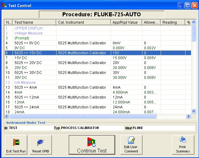
At any time the operator can return to ‘Test Control’ and repeat a test. If a measurement test is being performed the operator must select the previous test to set the output of the 5025 first. For example in the image above, to run test 7, test 6 must be selected first to set the output of the 5025 to 15V.
How To Change Comm Port for RS232 Command
It is possible to change the comm. port settings for a series of tests.
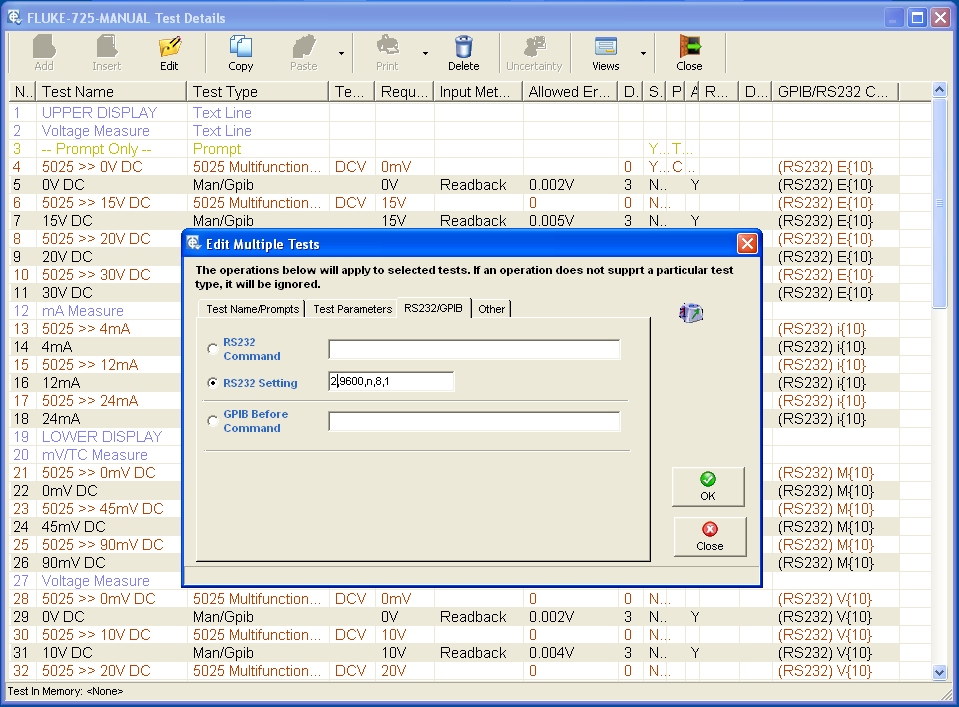
Highlight the tests which require changing, this will be all the Man/GPIB and 5075 Test Types. Click the ‘Edit’ button. The ‘Edit Multiple Test’ window will appear. Select the RS232/GPIB tab, then the RS232 Setting option.
Enter the value ‘<X>,9600,n,8,1’ where <X> is the comm. port.
Note: This will not change the RS232 Port settings for the Readback section. This has to be done on a test by test basis.
Readback Drivers
These are set in ‘EasyEdit>System Setup>Edit Readback Drivers’. The Fluke 725 is already set up and should not require any modification.
Prompt Images
A number of test prompt images are used to help the user connect the Fluke 725 to either the 5025 or 5075. These are located in C:\EC6\Pictures. The pictures are in jpg format.
Enabling RS232 on Fluke 725
By default the RS232 communication on the Fluke 725 is switched off. To turn on, press the source / measure button while powering up the Fluke 725. The display will show ‘RS232 ON’ to confirm this.
725 Resistance Measurements
We found that the 725 unit we have been using here is out of specification on the 3200Ω measurement range. We also confirmed this by using a precision 1067 decade box. Confirmation can also be made by verifying the 5025 output with the 5075DMM. (According to the Fluke certificate the 725 was calibrated less than 6 months ago).
Manual Input Procedure – Fluke 725 MANUAL
We have also produced a manual version of the procedure. This is used without automatic control of the Fluke 725. Values are entered by the operator as seen on the display or the Fluke 725 is set manually by the operator to source the required value.
Time 5065 DMM (6.5 Digit)
We found that the 5065 DMM was more than capable of measuring the outputs of the Fluke 725. If further units were to be purchased the 5065 could be considered. The 5075 could be used as a master station if any of the Fluke outputs were queried.
Agilent/HP 3458A DMM (8.5 Digit)
If you would prefer a 8.5 digit DMM, EasyCal does support the Agilent 3458A DMM. We use the 3458A in our own laboratories.
On-Line Setup and Training.
If required we can provide some on-line training and help with setup. We use Skyfex.com for desk top sharing. This enables us to see and control the desktop of your computer.